GALLERY
PRODUCT DESCRIPTION
Introduction to ARV or ARC valves
What are ARV or ARC valves?
ARV valve stands for Automatic Recirculation Valve.
An automatic recirculation valve is a multifunctional valve whose primary purpose is to ensure that a pre-determined minimum flow is assured through a centrifugal pump at all times. This is important as centrifugal pumps suffer from over heating and cavitation and can be permanently damaged if they run dry.

ARC valve is the abbreviation for Automatic Recirculation Control valve. The function of this valve is the same as that of a AR valve.
Centrifugal Pump Protection Scenarios
Centrifugal pumps transform mechanical energy into pressure energy by means of centrifugal force resulting from impeller rotation acting on the fluid within the pump. The pump requires a minimum liquid flow in order to avoid overheating. If a predefined minimum flow is not maintained, the pump can be permanently damaged. A number of different pump protection scenarios are reviewed below.
NON RETURN SCENARIO The pump has no back-flow prevention and therefore product will flow back through it once it has stopped. A non return valve (NRV) is therefore usually placed after the outlet of the pump. A reservoir is used to take the pumps output when there is no process demand.
CONTINUOUS FLOW SCENARIO A manual bypass or leakage path can be added to allow the required minimum flow back to the pump inlet. This system is simple and effective, but is in constant operation and therefore is inefficient and costly (energy costs).
CONTROL VALVE SCENARIO This comprehensive control valve solution is highly effective. In this scenario, a flow control valve is connected to a flow meter and allows the main line flow to be metered. As main line flow decreases the control valve opens to allow the correct minimum flow required. However, it is a highly capital intensive solution that requires flow metering equipment, control and non return valves. No reservoir is required.
ARV SOLUTION The previous approach stands and falls with the integrity of the control system and its associated cost. A safer system is to combine the non return valve, the bypass valve and the control valve into an interconnected unit, the so called "automatic recirculation valve". This valve closes when there is no flow, automatically opening the bypass line, which is sized for minimum flow. When the main line takes flow but less than minimum, the bypass line and the main line are both partially open.
Operation of a ARV Valve
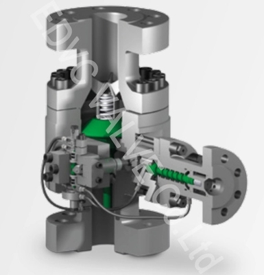
The heart of the recirculation valve is a main flow sensing check valve disc, which is flow sensitive, not pressure sensitive. The disc modulates to the demand for process flow at the same time helping ensure a minimum flow through the pump. This modulating characteristic results in a consistent, stable, and repeatable performance over full pressure range.

When the disc is set at full lift position, as in FIGURE 1, the bypass is closed. As process flow decreases, the reverse action occurs and the recirculation flow again increases. Flow enters the bypass element at the bottom of the disc assembly and is controlled by characterized orifices inside the disc stem. Flow continues through an annulus in the bypass bushing and is directed to the outlet of the valve. The valve provides for single phase flow in the bypass, eliminating the possibility of flashing or cavitation. This is accomplished by the valve design, and if necessary, external back pressure regulator.
As the disc lifts (FIGURE 2) in response to an increase in flow to the process, the bypass element which is integral to the disc, closes the bypass flow orifices reducing recirculation flow. Recirculation flow is controlled with disc position. This modulation feature assures that the total of process flow and recirculation flow exceed the minimum flow through the pump as specified by the pump manufacturer.
The disc is shown in the closed position in FIGURE 3. In this position there is no process flow and the bypass is fully open. This protects the pump against planned or accidental "dead heading" which can result from a closed down stream pump isolation valve or process control valve.


Leave your message